Address
304 North Cardinal St.
Dorchester Center, MA 02124
Work Hours
Monday to Friday: 7AM - 7PM
Weekend: 10AM - 5PM
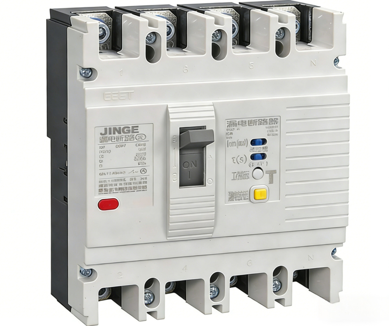
JINGE CM1L (M1L) series residual current molded case circuit breaker (MCCB) is an industrial-grade combined protection device integrating leakage protection, overload protection and short-circuit protection. Developed based on the mature CM1 MCCB platform and upgraded with high-sensitivity residual current release, this breaker is specially designed for industrial and commercial distribution systems requiring electric shock safety protection, fire prevention and equipment leakage monitoring.
CM1L MCCB operates reliably under AC 50/60Hz, 400/415V industrial power grid, covering rated current from 100A to 630A. It effectively detects leakage current caused by insulation aging, cable damage and equipment failure, and trips instantly to avoid electric shock accidents, electrical fire hazards and equipment burnout. Fully compliant with IEC 60947-2 and leakage protection standards, it is the most popular leakage MCCB model for overseas engineering projects and low-voltage distribution matching.
– Three-in-one integrated protection: Combines leakage residual current protection, overload long-time delay protection and short-circuit instantaneous protection in one unit, realizing full-range circuit safety control for industrial main and branch circuits.
– Fast leakage tripping & fire prevention: Quick response to leakage fault within 0.1s, effectively preventing electrical fire, electric shock injury and equipment damage caused by insulation deterioration in humid, dusty and harsh industrial environments.
– Mature and stable MCCB base platform: Adopts the same reliable mechanical structure and breaking performance as standard CM1 MCCB, with high short-circuit breaking capacity, strong anti-interference and low failure rate.
– Adjustable leakage sensitivity options: Supports 100mA, 300mA, 500mA and 1A residual current setting, suitable for personal protection, fire protection and equipment anti-leakage different requirements.
– Industrial-grade flame-retardant and durable structure: High-strength engineering plastic shell, heat-resistant, impact-resistant and anti-aging, suitable for long-term continuous operation in factories, construction sites and outdoor distribution occasions.
– Compatible installation and wiring flexibility: Standard MCCB size and mounting method, compatible with existing distribution cabinets, easy replacement and on-site wiring, no need to modify cabinet design.
– Most mainstream CE certified model for foreign trade: CM1L is the most widely used leakage MCCB in Yueqing for CE testing, with complete test reports, smooth customs clearance and high recognition by global buyers and engineering contractors.
| Model | XYCM1L-125 | XYCM1L-250 | XYCM1L-400 | XYCM1L-630 | XYCM1L-800 |
|---|---|---|---|---|---|
| Frame Current INM(A) | 125 | 250 | 400 | 630 | 800 |
| Rated Current IN(A) | 10、16、20、32、40、50、63、80、100 | 100、125、160、180、200、225 | 225、250、315、350、400 | 400、500、630 | 630、700、800 |
| Rated Insulation Voltage Ui(V) | 800 | 800 | 800 | 800 | 800 |
| Rated Operating Voltage Ue(V) | 230/400 | 230/400 | 230/400 | 230/400 | 400 |
| Rated Impulse Withstand Voltage Uimp(KV) | 8 | 8 | 8 | 8 | 8 |
| Pole Number | 2、3、4 | 2、3、4 | 2、3、4 | 2、3、4 | 2、3、4 |
| Breaking Capacity Level | L、M、H | L、M、H | L、M | L、M、H | L、M |
| Ultimate Short-Circuit Breaking Capacity Icu(KA)AC400V | 35、50、65 | 35、50、65 | 45、65 |
45、65 |
45、65 |
| Service Short-Circuit Breaking Capacity Ics(KA)AC400V | 22、30、35 | 22、30、35 | 25、25 | 22、30、35 | 22.5、32.5 |
| Arc Distance(mm) | 50 | 50 | 50 | 100 | – |
| Operating Performance (Times) | Times/Hour:120 | Times/Hour:60 | Times/Hour:60 | Times/Hour:60 | Times/Hour:20 |
| Energized:1500 De-energized:8500 |
Energized:1000 De-energized:7000 |
Energized:1000 De-energized:4000 |
Energized:1000 De-energized:4000 |
Energized:1000 De-energized:4000 |
|
| Rated Residual Operating Current △n(mA) | 100、300、500 | ||||
| Residual Current Protection Operating Time | 1I△n | 2I△n | – | 5I△n | 10I△n |
| Maximum Breaking Time(S) | Non-delayed:0.2 | Non-delayed:0.1 | – | Non-delayed:0.04 | Non-delayed:0.04 |
| Delayed:0.5/1.15/2.15 | Delayed:0.35/1/2 | – | Delayed:0.25/0.9/1.9 | Delayed:0.25/0.9/1.9 | |
| Ultimate Non-operating Time(ms)Delayed | 60/500/1000 | ||||
1. Ambient air temperature: The upper limit shall not exceed +40℃, the lower limit shall not be lower than -5℃, and the 24-hour average value shall not exceed +35℃.
2. The altitude of the installation site shall not exceed 2000m.
3. At the maximum temperature of +40℃, the relative humidity of the air shall not exceed 50%. Higher relative humidity is allowed at lower temperatures, e.g., 90% at 20℃. Special measures shall be taken for condensation occasionally caused by temperature changes.
4. Pollution degree: 3.
5. Installation category: Category II.
6. The circuit breaker should generally be installed vertically.
7. The external magnetic field of the circuit breaker installation site shall not exceed 5 times the earth’s magnetic field in any direction.
| Test Current Name | Setting Current Multiple In | Conventional Time h | Initial State | |
|---|---|---|---|---|
| In≤63A | In>63A | |||
| Conventional Non-tripping Current | 1.05 | ≥1 | ≥2 | Cold State |
| Conventional Tripping Current | 1.30 | <1 | <2 | Hot State |
The rated current of the instantaneous release for short-circuit protection is 10In with a standard tolerance of 20%.
Mechanical and electrical operating performance .
| Frame Grade Rated Current Inm(A) | Operating Cycles per Hour | With Current | Without Current | Total Times |
|---|---|---|---|---|
| 100 | 120 | 1500 | 8500 | 10000 |
| 225 | 120 | 1000 | 7000 | 8000 |
| 400 | 60 | 1000 | 4000 | 5000 |
| 630 | 60 | 1000 | 4000 | 5000 |
The overcurrent limit value that does not cause tripping in the main circuit is 6In.
The circuit breaker shall not malfunction under the impact voltage of 6kV.
Electric operating mechanism: When the circuit breaker is operated by the motor, it can reliably operate at any voltage between 85% and 110% of the rated control current voltage.
Shunt release: When the power supply voltage is any value between 70% and 110% of the rated control voltage, operating the shunt release can make the circuit breaker operate reliably.
Undervoltage release: When the power supply voltage is between 35% and 70% of the rated control voltage, the undervoltage release shall operate. When the power supply voltage is lower than 35%, the undervoltage release shall prevent the circuit breaker from closing. When the power supply voltage is equal to or greater than 85% of the rated working voltage of the undervoltage release, the circuit breaker shall be guaranteed to close reliably.
10. Arc distance ≤50mm (XYCM1L-100/225), ≤80mm (XYCM1L-400/630).
11. Cross-sectional area of connecting wires for circuit breakers (see Table 5 and Table 6)
| Rated Current(A) | 16/20 | 25 | 32 | 40/50 | 63 | 80 | 100 | 125/140 | 160 | 180/200/225 | 250 | 315/350 | 400 |
|---|---|---|---|---|---|---|---|---|---|---|---|---|---|
| Wire Cross-sectional Area (mm²) | 2.5 | 4 | 6 | 10 | 16 | 25 | 35 | 50 | 70 | 95 | 120 | 185 | 240 |
| Rated Current(A) | Cable Cross-sectional Area | Copper Bar Size | ||
|---|---|---|---|---|
| Quantity | Cross-sectional Area(mm²) | Quantity | Size(mm×mm) | |
| 500 | 2 | 150 | 2 | 30×5 |
| 630 | 2 | 185 | 2 | 40×5 |
1. Before installation, check whether the shell, handle, terminals, etc. of the circuit breaker are damaged, and verify that the technical data on the nameplate is consistent with the protected equipment.
2. The circuit breaker must be installed in accordance with regulations: 1, 3, 5 represent the power supply terminal, 2, 4, 6 represent the load terminal, and N represents the neutral pole.
3. When leaving the factory, the operating handle of the circuit breaker is in the free tripping position (middle position). To “open” or “close” the circuit breaker, first pull the operating handle to the “open” position to make the operating mechanism “re-engage”, then perform the “open” or “close” operation.
4. When adjusting the residual operating current and residual current breaking time according to actual conditions, the rotary switch should be adjusted to the required position. The overload protection, short-circuit protection, undervoltage release and shunt release of the circuit breaker have been adjusted according to technical requirements at the factory and sealed with red paint at the adjustment points, and shall not be adjusted by the user.
5. The residual current operation test of the circuit breaker shall be carried out once a month. Test method: When the circuit breaker is energized, press the test button to make the circuit breaker operate; tripping of the circuit breaker is qualified. If the circuit breaker cannot open when the test button is pressed, it indicates that the residual current protection function is lost, and the circuit breaker should be immediately removed and sent to the manufacturer for repair.
6. After the circuit breaker trips automatically, the cause must be identified and the fault eliminated before power can be supplied again.
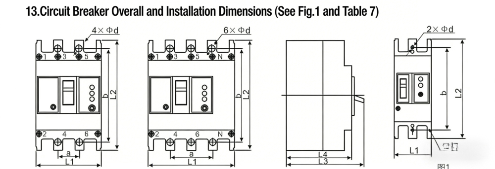
| Model | Pole Number | Outline Dimensions | Installation Dimensions | |||||
|---|---|---|---|---|---|---|---|---|
| L1 | L2 | L3 | L4 | a | b | Φd | ||
| XYCM1L-125L | 3 | 92max | 150max | 110max | 90max | 30±0.14 | 129±0.32 | 4×Φ4.5 |
| XYCM1L-125L | 4 | 122max | 150.5max | 92max | 72max | 60±0.28 | 129±0.32 | 6×Φ4.5 |
| XYCM1L-125L | 2 | 62max | 150.5max | 110max | 90max | / | 129±0.32 | 2×Φ4.5 |
| XYCM1L-125L | 3 | 92.5max | 150.5max | 110max | 90max | 30±0.14 | 129±0.32 | 4×Φ4.5 |
| XYCM1L-125L | 4 | 122.5max | 150max | 94max | 89.5max | 60±0.28 | 129±0.32 | 6×Φ4.5 |
| XYCM1L-250 | 3 | 107max | 165.5max | 110max | 88max | 35±0.16 | 126±0.32 | 4×Φ4.5 |
| XYCM1L-250 | 4 | 142max | 165.5max | 92max | 72max | 70±0.32 | 126±0.32 | 6×Φ4.5 |
| XYCM1L-250 | 3 | 107max | 165.5max | 110max | 88max | 35±0.16 | 126±0.32 | 4×Φ4.5 |
| XYCM1L-250 | 2 | 75max | 165.5max | 110max | 88max | / | 126±0.32 | 2×Φ4.5 |
| XYCM1L-250 | 4 | 142max | 165.5max | 107.5max | 88max | 70±0.32 | 126±0.32 | 6×Φ4.5 |
| XYCM1L-400L, M | 3 | 150max | 258max | 150max | 105max | 44±0.20 | 195±0.32 | 4×Φ7 |
| XYCM1L-400L, M | 4 | 198max | 258max | 150max | 106max | 88±0.40 | 195±0.32 | 6×Φ7 |
| XYCM1L-630L, M | 3 | 212max | 282max | 152max | 108max | 70±0.20 | 243±0.50 | 4×Φ7 |
| XYCM1L-630L, M | 4 | 282max | 282max | 152max | 110max | 140±0.40 | 243±0.50 | 6×Φ7 |