Address
304 North Cardinal St.
Dorchester Center, MA 02124
Work Hours
Monday to Friday: 7AM - 7PM
Weekend: 10AM - 5PM
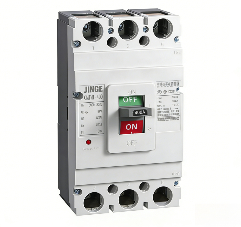
JINGE XYCM1 Series Molded Case Circuit Breaker (MCCB) is a professional industrial-grade protection device designed for power distribution and motor protection. It is suitable for AC 50/60Hz, rated operating voltage up to 690V, and rated current from 63A to 800A.
The breaker provides full protection against overload, short circuit and under-voltage faults, ensuring safe operation of power systems, cables, transformers, motors and electrical equipment. With high breaking capacity, short arc-flash distance, anti-vibration structure and flexible vertical/horizontal installation, XYCM1 is widely used in harsh industrial and construction environments while offering easy visual inspection via its transparent housing.
| Item | XYCM1-63 | XYCM1-100 | XYCM1-125 | XYCM1-250 | XYCM1-400 | XYCM1-630 | XYCM1-800 |
|---|---|---|---|---|---|---|---|
| Frame Current Inm (A) | 63 | 100 | 125 | 250 | 400 | 630 | 800 |
| Rated Current In (A) | (6), 10, 16, 20, 25, 32, 40, 50, 63 | 10, 16, 20, 32, 40, 50, 63, 80, 100 | 80, 100, 125 | 100, 125, 160, 180, 200, 225, 250 | 225, 250, 315, 350, 400 | 400, 500, 630 | 630, 700, 800 |
| Rated Insulation Voltage Ui (V) | 500 | 690 | 800 | 800 | 690 | 690 | 690 |
| Rated Operating Voltage Ue (V) | 400 | 400 | 230 / 400 | 230 / 400 | 400 | 400 | 400 |
| Rated Impulse Withstand Voltage Uimp (kV) | 6 | 6 | 8 | 8 | 6 | 6 | 6 |
| No. of Poles | 3 / 4 | 3 / 4 | 2 / 3 / 4 | 2 / 3 / 4 | 3 / 4 | 3 / 4 | 3 / 4 |
| Breaking Class | L / M | L / M | L / M / H | L / M / H | L / M | L / M | L / M |
| Ultimate Breaking Capacity Icu (kA) AC400V | 10 / 15 / 35 | 35 / 50 | 35 / 50 / 65 | 35 / 50 / 65 | 45 / 65 | 45 / 65 | 50 / 65 |
| Service Breaking Capacity Ics (kA) AC400V | 5 / 10 / 25 | 25 / 30 | 25 / 30 / 50 | 25 / 30 / 50 | 22.5 / 32.5 | 22.5 / 32.5 | 25 / 32.5 |
| Arc Flash Distance (mm) | ≤50 | ≤50 | ≤50 | ≤50 | ≤100 | ≤100 | ≤100 |
| Operating Cycles / Hour | 120 | 120 | 120 | 120 | 60 | 60 | 20 |
| Mechanical Life With Load | 4000 | 3000 | 3000 | 1500 | 1500 | 1000 | 500 |
| Mechanical Life No Load | 6000 | 7000 | 7000 | 6500 | 6500 | 4000 | 2500 |
JINGE XYCM1 MCCB is designed for industrial and infrastructure power distribution systems. It is widely applied in main distribution boards, sub-distribution boxes, motor control centers (MCC), factory production lines, power plants, construction sites, mining, metallurgy, petrochemical and commercial building power supply systems. Typical applications include main incoming protection, feeder circuit protection, motor protection, pump and compressor protection, generator set output protection, and large electrical equipment power supply. Its high reliability, easy installation and maintenance-friendly transparent design make it an ideal choice for global contractors, electrical integrators, plant maintenance and industrial electrical distributors.
| Test Current Name | I/Ih | Conventional Time (Ih≤63) | Conventional Time (63<In≤250) | Conventional Time (In≥250) | Initial State | Ambient Temperature |
|---|---|---|---|---|---|---|
| Conventional Non-Tripping Current | 1.05 | ≥1h | ≥2h | ≥2h | Cold State | +30℃ |
| Conventional Tripping Current | 1.30 | <1h | <2h | <2h | Hot State | +30℃ |
| Recoverable Time | 3.0 | 5s | 8s | 12s | Cold State | +30℃ |
| Test Current Name | I/Ih | Conventional Time (10≤In≤250) | Conventional Time (250≤In≤630) | Initial State | Ambient Temperature |
|---|---|---|---|---|---|
| Conventional Non-Tripping Current | 1.0 | ≥2h | ≥2h | Cold State | +40℃ |
| Conventional Tripping Current | 1.2 | <2h | <2h | Hot State | +40℃ |
| – | 1.5 | ≤4min | ≤8min | Cold State | +40℃ |
| Recoverable Time | 7.2 | 4s≤T≤10s | 6s≤T≤20s | Hot State | +40℃ |
| Inm (A) | For Distribution | For Motor Protection |
|---|---|---|
| 63, 100, 125, 250, 400 | 10In | 12In |
| 630 | 5In and 10In | – |
| 800 | 10In | – |
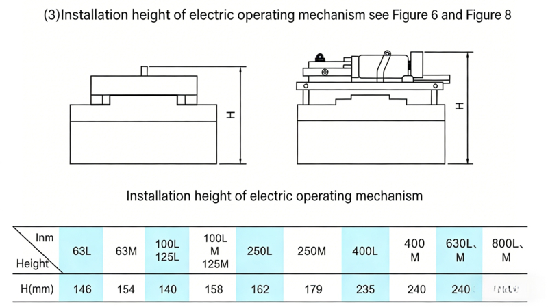
(1) The rated operating voltage of the electric operating mechanism includes: AC50Hz 110V, 230V; DC110V, 220V and other types.
(2) The power consumption of the motor of the electric operating mechanism is shown in Table 7.
| Circuit Breaker for Matching | Starting Current (A) | Power Consumption (W) | Circuit Breaker for Matching | Starting Current (A) | Power Consumption (W) |
|---|---|---|---|---|---|
| XYCM1-63 | ≤5 | 1100 | XYCM1-400 | ≤5.7 | 1200 |
| XYCM1-100(125) | ≤7 | 1540 | XYCM1-630 | ≤5.7 | 1200 |
| XYCM1-125 | ≤8.5 | 1870 | – | – | – |
1. Close and open the circuit breaker several times to check whether the operating mechanism of the circuit breaker is stuck and whether the mechanism action is reliable.
2. The “N”, “1”, “3”, “5” of the breaker are incoming terminals, and “N”, “2”, “4”, “6” are outgoing terminals, which are not allowed to be installed reversely.
3. The cross-sectional area of the connecting wire selected for the circuit breaker wiring must be adapted to the rated current. For the cross-sectional area of the main circuit wire when using copper wire or copper bar, refer to Table
| Rated Current (A) | 10 | 16 20 |
25 | 32 | 40 50 |
63 | 80 | 100 | 125 140 |
160 | 180 200 225 |
250 | 315 350 |
400 |
|---|---|---|---|---|---|---|---|---|---|---|---|---|---|---|
| Wire Cross-Sectional Area (mm²) | 1.5 | 2.5 | 4 | 6 | 10 | 16 | 25 | 35 | 50 | 70 | 95 | 120 | 185 | 240 |
| Rated Current (A) | Cable | Copper Bar | |||
|---|---|---|---|---|---|
| – | Cross-Sectional Area (mm²) | Quantity | Size (mm×mm) | Size (mm×mm) | Quantity |
| 500 | 150 | 2 | 30×5 | – | 2 |
| 630 | 185 | 2 | 40×5 | – | 2 |
| 800 | 240 | 3 | 50×5 | – | 2 |
Confirm that the terminal connections and fixing screws are tight and free of looseness before use.
The single-mounted circuit breaker shall be vertically fixed in a dry and ventilated place. It shall be easy to maintain and operate, with a distance of ≥1.5 meters from the ground.
6. Confirm that there is no short circuit or ground fault between the terminals or exposed live parts.
7. After the circuit breaker trips due to overload, check the cause to eliminate the fault, and reset the bimetallic sheet inside the circuit breaker before closing and energizing.
| Type | Item | XYCM1-63 | XYCM1-100, 125 | XYCM1-250 | XYCM1-400 | XYCM1-630 | XYCM1-800 | ||||||
|---|---|---|---|---|---|---|---|---|---|---|---|---|---|
| L | M | L | M | L | M | L | M | L | M | L | M | ||
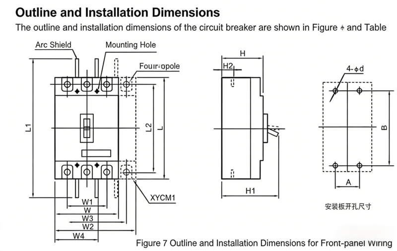
| Front Wiring | W | 78 | 92 | 107 | 150 | 182 | 210 | ||||||
| W1 | 50 | 60 | 70 | 96 | 118 | 140 | |||||||
| W2 | 103 | 122 | 142 | 198 | 240 | 280 | |||||||
| W3 | 75 | 90 | 105 | 144 | 174 | 211 | |||||||
| L | 135 | 150 | 165 | 257 | 270 | 280 | |||||||
| L1 | 169 | 185 | 295 | 456 | 476 | 490 | |||||||
| L2 | 117 | 132 | 144 | 224 | 234 | 243 | |||||||
| H | 74 | 82 | 68 | 86 | 86 | 103 | 107 | 107 | 112 | 116 | 116 | 116 | |
| H1 | 90.5 | 98.5 | 86 | 104 | 110 | 127 | 155 | 155 | 160 | 168 | 168 | 168 | |
| H2 | 20.5 | 24 | 24 | 38 | 42 | 41.5 | |||||||
| H3 | 52 | 63 | 52 | 60.5 | 61 | 74 | |||||||
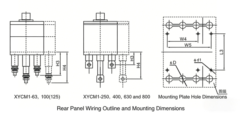
| Rear Wiring | H4 | 75 | 103 | 97 | 120.5 | 121 | 74 | ||||||
| W4 | 60 | 72 | 87 | 124 | 156 | 178 | |||||||
| W5 | 85 | 102 | 122 | 172 | 214 | – | |||||||
| φd1 | 5.5 | 5.5 | 5.5 | 6.5 | 7 | 7 | |||||||
| φD | 18 | 22 | 24 | 32 | 40 | 48 | |||||||
| L3 | 87 | 90 | 93 | 164 | 164 | 158 | |||||||
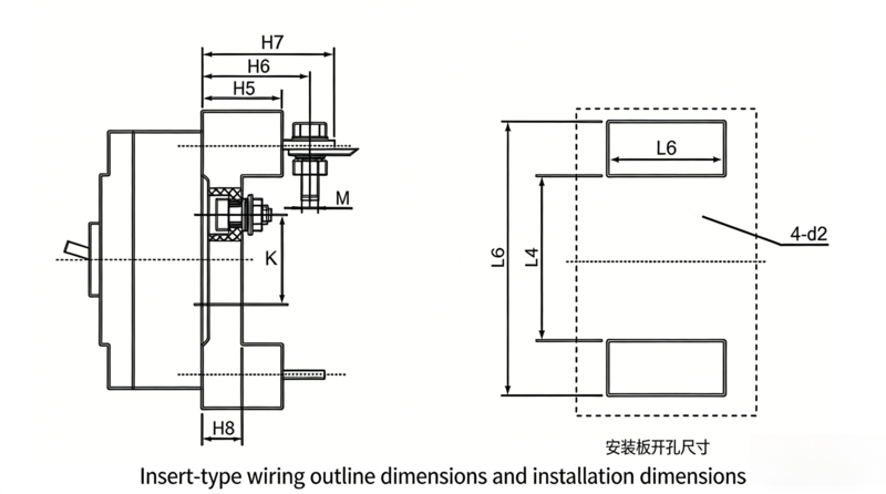
| Plug-in | L4 | 90 | 87 | 83 | 160 | 177 | 177 | ||||||
| L5 | 146 | 172 | 190 | 282 | 302 | – | |||||||
| L6 | 85 | 101.5 | 117 | 151 | 226 | 226 | |||||||
| H5 | 28 | 50 | 50.5 | 60.5 | 91 | 91 | |||||||
| H6 | 36 | 64 | 71.5 | 83.5 | 92 | – | |||||||
| H7 | – | 76 | 86.5 | 106.5 | 110 | – | |||||||
| H8 | – | 17.5 | 17.5 | 21 | 21 | – | |||||||
| K | 60 | 62 | 54 | 128 | 142 | 142 | |||||||
| C | 50 | 60 | 70 | 60 | 105 | 105 | |||||||
| φd2 | 5.5 | 6.5 | 6.5 | 8.5 | 12 | 12 | |||||||
| M | 5 | 8 | 8 | 12 | 14 | 14 | |||||||
| A | 25 | 30 | 35 | 44 | 58 | 70 | |||||||
| B | 117 | 129 | 126 | 194 | 200 | 243 | |||||||
| Installation Dimensions | φd | 3.5 | 4.5 | 4.5 | 7 | 7 | 7 | ||||||