Address
304 North Cardinal St.
Dorchester Center, MA 02124
Work Hours
Monday to Friday: 7AM - 7PM
Weekend: 10AM - 5PM
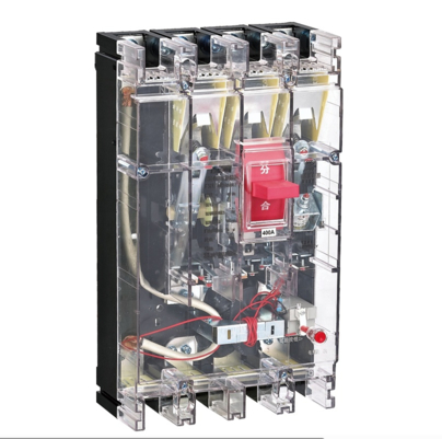
DZ20LE sesirs residual current circuit breakers are current-operated electronic residual current protective devices. They are mainly suitable for AC 50Hz, rated operating voltage 380V, and rated current up to 630A distribution networks. They are mainly used to provide overload and short-circuit protection for equipment; to provide indirect contact protection for persons against the risk of increased voltage to earth due to insulation damage; to provide protection against fire hazards caused by long-term existing earth fault currents that cannot be detected by overcurrent protective devices; they can also be used for power distribution and line protection, as well as for infrequent switching of lines and infrequent starting of motors under normal conditions.
This series of products complies with the requirements of GB/T 14048.2 standard.
The residual current circuit breakers of this series are Type AC residual current circuit breakers.
1. The residual current breaking time of the residual current circuit breaker is shown in Table 1.
General Type Residual Current Breaking Time
| Residual Current | I△n | 2I△n | 5I△n | 10I△n |
|---|---|---|---|---|
| Maximum Breaking Time (s) | 0.1 | 0.05 | 0.04 | 0.04 |
2. Regulations and parameters are shown in Table 2.
Specifications and Parameters
| Frame Grade Rated Current Imm (A) | Pole Number | Rated Voltage Ue (V) | Rated Current In (A) | Rated Ultimate Short-circuit Breaking Capacity Icu (kA) | Rated Service Short-circuit Breaking Capacity Ics (kA) | Arc Distance (mm) | Rated Residual Operating Current I△n (mA) | Rated Residual Non-operating Current I△no (mA) |
|---|---|---|---|---|---|---|---|---|
| DZ20LE-160 | 3N | 380 | 50, 63, 80, 100, 125, 160 | 12 | 8 | ≤50 | 50 | 25 |
| 100 | 50 | |||||||
| 150 | 75 | |||||||
| 200 | 100 | |||||||
| 300 | 150 | |||||||
| DZ20LE-250 | 100, 125, 160, 180, 200, 250 | 15 | 10 | ≤60 | 100 | 50 | ||
| 150 | 75 | |||||||
| 200 | 100 | |||||||
| 300 | 150 | |||||||
| 500 | 250 | |||||||
| DZ20LE-400 | 200, 250, 315, 350, 400 | 20 | 14 | ≤60 | 100 | 50 | ||
| 200 | 100 | |||||||
| 300 | 150 | |||||||
| DZ20LE-630 | 400, 500, 630 | 25 | 16 | ≤100 | 200 | 100 | ||
| 300 | 150 | |||||||
| 500 | 250 |
Note: The arc distance in the table is ≤30mm for up, down, left, right, front and rear directions.
(1) The overcurrent protection characteristics of residual current circuit breakers for distribution protection are shown in Table 3.
Overcurrent Protection Characteristics of Residual Current Circuit Breakers for Distribution Use
| Ambient Air Temperature | Test Current/Rated Current | Ambient Air Temperature | Initial State | |
|---|---|---|---|---|
| In≤63A | In>63A | |||
| +30±2℃ | 1.05 | No Tripping within <1h | No Tripping within 2h | Start from Cold State |
| 1.30 | Tripping within <1h | Tripping within 2h | Start from Hot State | |
| 3.0 | Recoverable Time ≥5s | Recoverable Time ≥8s | Start from Cold State | |
| At Any Suitable Temperature | 10.0 | Tripping within <0.2s | Start from Cold State | |
| +20±2℃ | 1.05 | No Tripping within 1h | No Tripping within 2h | Start from Cold State |
| 1.30 | Tripping within <1h | Tripping within 2h | Start from Hot State | |
(2) The overcurrent protection characteristics of residual current circuit breakers for motor protection are shown in Table 4.
Overcurrent Protection Characteristics of Residual Current Circuit Breakers for Motor Protection
| Ambient Air Temperature | Test Current/Rated Current | Test Time | Initial State |
|---|---|---|---|
| +40±2℃ | 1.0 | No Tripping within 2h | Start from Cold State |
| 1.2 | Tripping within 2h | Start from Hot State | |
| 1.5 | Tripping within 4min | Start from Hot State | |
| 7.2 | 4s < T < 10s | Start from Cold State | |
| At Any Suitable Temperature | 12.0 | Tripping within <0.2s | Start from Cold State |
4. Instantaneous Tripping Characteristics of Overcurrent Release under Short-circuit Condition
The overcurrent release trips instantaneously under short-circuit condition, and the accuracy of its setting value is ±20%.
5. Electrical Clearance and Creepage Distance
The electrical clearance of the residual current circuit breaker is not less than 5.5mm, and the creepage distance is not less than 10mm.
6. Rated Impulse Withstand Current: 6kV.
1. Ambient air temperature range: -5℃ to +40℃; the daily average shall not exceed +35℃.
Note: For operating conditions where the ambient air temperature exceeds +40℃ or is lower than -5℃, the user shall consult the manufacturer when placing an order.;
2. Altitude: The altitude of the installation site shall not exceed 2000m.
3.Atmospheric conditions: At the maximum temperature of +40℃, the relative humidity of the air shall not exceed 50%. Higher relative humidity is allowed at lower temperatures, e.g., up to 90% at 20℃, and consideration shall be given to condensation on the product surface due to temperature changes.
4. Pollution degree: Class 3.
5. Installation category: Class II.
6. Installation conditions: Installed indoors individually or in a distribution cabinet. The installation site shall be free from obvious impact vibration, rain and snow; the upper terminal shall be connected to the power supply, and the lower terminal to the load, reverse connection is strictly prohibited. The inclination angle between the installation surface and the vertical plane shall not exceed 5°..
7. The external magnetic field near the installation site of the circuit breaker shall not exceed 5 times the geomagnetic field in any direction.
1. Structure Composition
This series of residual current circuit breakers are current-operated earth leakage protection circuit breakers. The main components include: the circuit breaker (including the overcurrent release), zero-sequence current transformer, electronic amplifier components, residual current release, and test device. All components are housed in a single plastic enclosure.
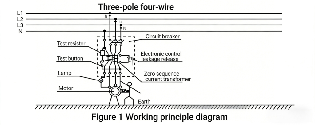
2. Working Principle of Earth Leakage Protection
When an earth leakage exists in the protected circuit, the vector sum of the currents passing through the zero-sequence current transformer is not zero (i.e.,I1+I2+I3=0), which induces a voltage in the secondary winding of the zero-sequence current transformer.
When the earth leakage current reaches the rated operating current value of the residual current circuit breaker, the current signal output by the zero-sequence current transformer is sampled and amplified by the electronic component board. The driving components on the electronic board actuate the residual current release within the specified time, which then pushes the residual current circuit breaker to trip and cut off the power supply via the drawbar, thus achieving the earth leakage protection function. Its working principle diagram is shown in Figure 1.
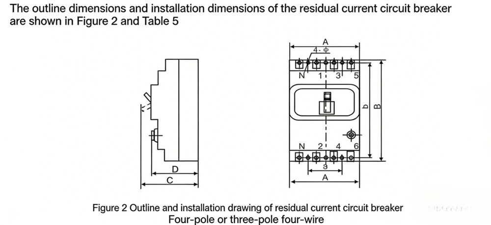
| Product Model | Pole Number | Outline Dimensions (mm) | Installation Dimensions (mm) | |||||
|---|---|---|---|---|---|---|---|---|
| A | B | C | D | a | b | Mounting Hole Φ | ||
| DZ20LE-160 | 3N | 143 | 225 | 105 | 90 | 70±0.37 | 204±0.57 | Φ4.5 |
| DZ20LE-250 | 3N | 144 | 276 | 143 | 100 | 70±0.37 | 240±0.65 | Φ4.5 |
| DZ20LE-400, 630 | 3N | 206 | 360 | 149 | 116 | 102±0.43 | 326±0.70 | Φ7 |
1. Installation of Residual Current Circuit Breaker
(1) Before installation, check whether the basic parameters on the nameplate meet the application requirements. Operate it manually several times to ensure flexible and reliable action, and confirm that it is intact and undamaged before installation.
(2) The residual current circuit breaker shall be installed vertically. The upward position of the handle is the contact closing position. The upper part of the residual current circuit breaker is the power supply side (i.e., incoming terminal), and the lower part is the load side (i.e., outgoing terminal). Reverse connection is strictly prohibited.
(3) When installing the residual current circuit breaker, the cross-sectional area of the selected connecting wire must be compatible with the rated current. Refer to Table 6 for insulated copper wires or copper bars.
(4) To prevent phase-to-phase arc short-circuit, arc barriers shall be inserted for insulation.
| Rated Current (A) | 40/50 | 63 | 80 | 100 | 125 | 160 | 180/200 | 225/250 | 315 | 350/400 |
|---|---|---|---|---|---|---|---|---|---|---|
| Wire Cross-sectional Area (mm²) | 10 | 16 | 25 | 35 | 50 | 70 | 95 | 120 | 185 | 240 |
| Rated Current (A) | Copper Wire (mm²) | Copper Bar (mm²) | Rated Current (A) | Copper Wire (mm²) | Copper Bar (mm²) | |||||
| 400 < In ≤500 | 2-150 | – | 630 < In | 2-240 | 2-50×5 | |||||
| 500 < In ≤630 | 2-185 | 2-40×5 | ||||||||
(1) During wiring, the residual current circuit breaker must strictly distinguish between the neutral wire and the protective earthing wire. When connecting a 3-pole 4-wire or 4-pole residual current circuit breaker, the neutral wire shall be connected to the N pole of the circuit breaker. The output terminal of the neutral wire of the residual current circuit breaker shall not be used as a protective earthing wire again (i.e., no repeated earthing or connection to equipment casing), and can only be used as a current-carrying neutral wire. If a protective earthing wire needs to be connected, it must be connected before the input terminal of the residual current circuit breaker. Otherwise, the residual current circuit breaker cannot operate normally.
(2) When the operating handle of the residual current circuit breaker shows the “ON” position, it indicates that the circuit is closed and connected; when the handle shows the “OFF” position, it indicates that the circuit is open and disconnected.
(3) After installation and before closing, the operating handle of the residual current circuit breaker shall be in the “OFF” or “O” position before closing.
(4) A separately installed residual current circuit breaker should be easy to operate and maintain, and the recommended height from the ground is generally 1500mm.
(5) After installation and a certain period of use, the residual current circuit breaker shall press the “Test Button” to check whether the earth leakage protection performance is normal. If the residual current circuit breaker can break normally when the “Test Button” is pressed, it indicates that the earth leakage protection characteristic is normal; if the residual current circuit breaker cannot break when the “Test Button” is pressed, it indicates that the earth leakage protection function has failed, and it should be removed for replacement or sent to the manufacturer for maintenance in time.
(6) The overload, short-circuit and earth leakage protection characteristics of the residual current circuit breaker are all set by the manufacturer and cannot be disassembled and adjusted arbitrarily during use. Otherwise, you will be responsible for all consequences.
(7) If the residual current circuit breaker breaks due to earth leakage in the protected circuit or earth leakage caused by insulation damage during use, the operating handle will be in the tripped position (middle position). The cause should be identified and the fault eliminated. Then, first flip the operating handle downward to “reset” the operating mechanism before closing and using it again. Otherwise, the residual current circuit breaker cannot operate normally.
(1) When selecting the rated residual operating current value of the residual current circuit breaker, full consideration shall be given to the normal leakage current value of the protected circuit and various equipment. If possible, the normal leakage current value of the circuit and equipment can be measured on site.
(2) When selecting the rated residual non-operating current value of the residual current circuit breaker, it shall not be less than twice the maximum normal leakage current value of the circuit and equipment.
(3) When selecting the rated current of the residual current circuit breaker, the appropriate rated current, rated residual operating current and breaking time shall be selected according to the specific requirements of the protected object. Otherwise, the correct protection effect cannot be achieved.
Correct selection and installation of the residual current circuit breaker is an important link to achieve normal protection. If installed improperly or wired incorrectly, the residual current circuit breaker cannot operate normally, and may even malfunction or refuse to operate.
(1) Main Causes and Solutions for Malfunction
① Malfunction caused by earthing of the neutral wire on the load side of a 3-pole 4-wire residual current circuit breaker:
Earthing of the neutral wire on the load side will make the vector sum of the currents flowing into the zero-sequence current transformer non-zero, causing the residual current circuit breaker to malfunction.
Troubleshooting: Remove the earthing of the neutral wire on the load side. If you must connect the protective earthing wire, please use a three-phase five-wire power supply, because only the non-current-carrying earthing wire can achieve real earthing protection.
② Malfunction caused by using single-pole load on the load side of a 3-pole residual current circuit breaker:
3-pole residual current circuit breakers are mostly used for motor (delta connection) protection, and the neutral wire does not pass through the zero-sequence current transformer. Therefore, the residual current circuit breaker will break as long as a single-phase load is used.
Troubleshooting: When both three-phase load and single-phase load are needed in a three-phase power supply, be sure to use a three-phase four-wire or four-pole residual current circuit breaker.
③ Malfunction caused by excessive normal leakage current of the circuit and equipment:
Excessively long wires on the load side of the residual current circuit breaker will increase the normal leakage current, which may cause the residual current circuit breaker to malfunction; or the insulation of the equipment decreases, and the earth leakage current increases, causing the residual current circuit breaker to malfunction.
Troubleshooting: Minimize the length of the wires, perform insulation maintenance on the equipment, or select a residual current circuit breaker with an appropriate earth leakage operating current after actually measuring the leakage current value.
④ Malfunction caused by the connection of neutral wires of two residual current circuit breakers on the branch:
When there is an unbalanced load, the unbalanced current cannot all return along this branch, and part of the unbalanced current must return along other branches, causing the two residual current circuit breakers to malfunction.
Troubleshooting: Connect the neutral wire on the power supply side of the residual current circuit breaker.
(3) Electrical Equipment with and without Earth Leakage Protector
When electrical equipment with and without earth leakage protector share a set of earthing device, if an earth leakage fault occurs on the equipment without earth leakage protector, the dangerous touch voltage will be transmitted to the equipment with earth leakage protector through the common earthing device. When touching the equipment casing, the electric shock current does not pass through the earth leakage protector, thus losing the earth leakage protection function and causing electric shock hazard.
Troubleshooting: The earthing protection devices of electrical equipment with and without earth leakage protector shall be earthed separately.
Users shall specify the following contents when placing an order:
1. Name and model of the residual current circuit breaker;
2. Rated current (A) of the residual current circuit breaker;
3. Rated residual operating current (mA) of the residual current circuit breaker;
4. Residual current breaking time: standard type or time-delay type;
5. Protection type;
6. Pole number and quantity.
Note: If users have other special requirements for ordering, please contact the manufacturer.
Example: Ordering CDZ20L-400 residual current circuit breaker, rated current 400A, rated residual operating current 200mA, for distribution use, total 100 units.
It should be written as: CDZ20L-400/3N300, 400A, 200mA, 100 units.