Address
304 North Cardinal St.
Dorchester Center, MA 02124
Work Hours
Monday to Friday: 7AM - 7PM
Weekend: 10AM - 5PM
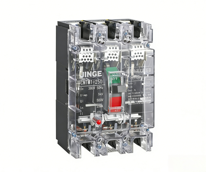
The JINGE CM1 Series Transparent Molded Case Circuit Breaker (MCCB) is a heavy-duty industrial-grade power protection device, designed and manufactured referring to the high-standard design specifications of CHINT, DELIXI, TENGEN and international mainstream low-voltage electrical brands. This transparent-shell MCCB is specially developed for industrial main power incoming lines, distribution branch circuits and motor load protection, balancing professional industrial performance, visual safety inspection and long-term operational stability.
Different from ordinary household circuit breakers, the XYCM1 transparent MCCB focuses on harsh industrial and engineering power supply environments, featuring high breaking capacity, strong overload resistance, excellent arc extinction performance and durable mechanical structure. The visible transparent shell design allows engineers to directly observe the internal contact working status, quickly judge circuit faults, greatly reduce daily maintenance difficulty and after-sales troubleshooting costs. Fully compliant with IEC 60947-2 international industrial standards, it supports complete CE certification documents, ensuring smooth customs clearance and stable long-term operation for global industrial projects and electrical distributors.
– Visual Transparent Shell Design for Easy Maintenance: The transparent molded shell structure makes internal contacts and working state clearly visible, solving the industry pain point of traditional opaque MCCB that cannot quickly check hidden faults, saving maintenance time and reducing on-site inspection costs for engineering teams.
– High Industrial Breaking & Short-Circuit Resistance Performance: Adopts optimized arc extinction system and high-strength conductive components, with high rated short-circuit breaking capacity, effectively avoiding equipment burnout, power grid impact and project shutdown losses caused by sudden short-circuit faults in industrial heavy-load circuits.
– Strong Overload & Thermal Stability for Harsh Environments: Matches professional thermo-magnetic tripping system, stable tripping action without misoperation or refusal; adapts to high temperature, dust and long-term continuous power supply working conditions, solving the problem of frequent tripping or failure of inferior breakers in factory continuous production.
– Complete Protection Functions for Full-Circuit Safety: Integrates overload long-time delay protection, short-circuit instantaneous protection and phase failure protection (optional), effectively protecting power distribution equipment, production machinery and personal safety, avoiding project economic losses caused by unprotected circuit faults.
– Dual Installation & Flexible Wiring Adaptability: Supports vertical and horizontal dual installation methods, compatible with various industrial distribution cabinets and power box installation standards worldwide; diversified wiring methods meet different on-site engineering wiring requirements, strong compatibility and wide applicability.
– High-Grade Flame-Retardant & Impact-Resistant Material: Adopts industrial reinforced engineering plastic shell, with flame retardant, high temperature resistance, impact resistance and anti-aging characteristics, not easy to deform and burn in harsh industrial environments, long service life and low replacement frequency.
– Standardized Production & Complete Certification Support: Produced in strict accordance with IEC industrial standards, with complete test reports and CE certification files, solving the pain points of difficult customs clearance and unqualified project acceptance for overseas importers and engineering contractors.
| Item | XYCM1-63 | XYCM1-100 | XYCM1-125 | XYCM1-250 | XYCM1-400 | XYCM1-630 | XYCM1-800 |
|---|---|---|---|---|---|---|---|
| Frame Current Inm (A) | 63 | 100 | 125 | 250 | 400 | 630 | 800 |
| Rated Current In (A) | (6), 10, 16, 20, 25, 32, 40, 50, 63 | 10, 16, 20, 32, 40, 50, 63, 80, 100 | 80, 100, 125 | 100, 125, 160, 180, 200, 225, 250 | 225, 250, 315, 350, 400 | 400, 500, 630 | 630, 700, 800 |
| Rated Insulation Voltage Ui (V) | 500 | 690 | 800 | 800 | 690 | 690 | 690 |
| Rated Operating Voltage Ue (V) | 400 | 400 | 230 / 400 | 230 / 400 | 400 | 400 | 400 |
| Rated Impulse Withstand Voltage Uimp (kV) | 6 | 6 | 8 | 8 | 6 | 6 | 6 |
| No. of Poles | 3 / 4 | 3 / 4 | 2 / 3 / 4 | 2 / 3 / 4 | 3 / 4 | 3 / 4 | 3 / 4 |
| Breaking Class | L / M | L / M | L / M / H | L / M / H | L / M | L / M | L / M |
| Ultimate Breaking Capacity Icu (kA) AC400V | 10 / 15 / 35 | 35 / 50 | 35 / 50 / 65 | 35 / 50 / 65 | 45 / 65 | 45 / 65 | 50 / 65 |
| Service Breaking Capacity Ics (kA) AC400V | 5 / 10 / 25 | 25 / 30 | 25 / 30 / 50 | 25 / 30 / 50 | 22.5 / 32.5 | 22.5 / 32.5 | 25 / 32.5 |
| Arc Flash Distance (mm) | ≤50 | ≤50 | ≤50 | ≤50 | ≤100 | ≤100 | ≤100 |
| Operating Cycles / Hour | 120 | 120 | 120 | 120 | 60 | 60 | 20 |
| Mechanical Life With Load | 4000 | 3000 | 3000 | 1500 | 1500 | 1000 | 500 |
| Mechanical Life No Load | 6000 | 7000 | 7000 | 6500 | 6500 | 4000 | 2500 |
| Test Current Name | I/Ih | Conventional Time (Ih≤63) | Conventional Time (63<In≤250) | Conventional Time (In≥250) | Initial State | Ambient Temperature |
|---|---|---|---|---|---|---|
| Conventional Non-Tripping Current | 1.05 | ≥1h | ≥2h | ≥2h | Cold State | +30℃ |
| Conventional Tripping Current | 1.30 | <1h | <2h | <2h | Hot State | +30℃ |
| Recoverable Time | 3.0 | 5s | 8s | 12s | Cold State | +30℃ |
| Test Current Name | I/Ih | Conventional Time (10≤In≤250) | Conventional Time (250≤In≤630) | Initial State | Ambient Temperature |
|---|---|---|---|---|---|
| Conventional Non-Tripping Current | 1.0 | ≥2h | ≥2h | Cold State | +40℃ |
| Conventional Tripping Current | 1.2 | <2h | <2h | Hot State | +40℃ |
| – | 1.5 | ≤4min | ≤8min | Cold State | +40℃ |
| Recoverable Time | 7.2 | 4s≤T≤10s | 6s≤T≤20s | Hot State | +40℃ |
| Inm (A) | For Distribution | For Motor Protection |
|---|---|---|
| 63, 100, 125, 250, 400 | 10In | 12In |
| 630 | 5In and 10In | – |
| 800 | 10In | – |
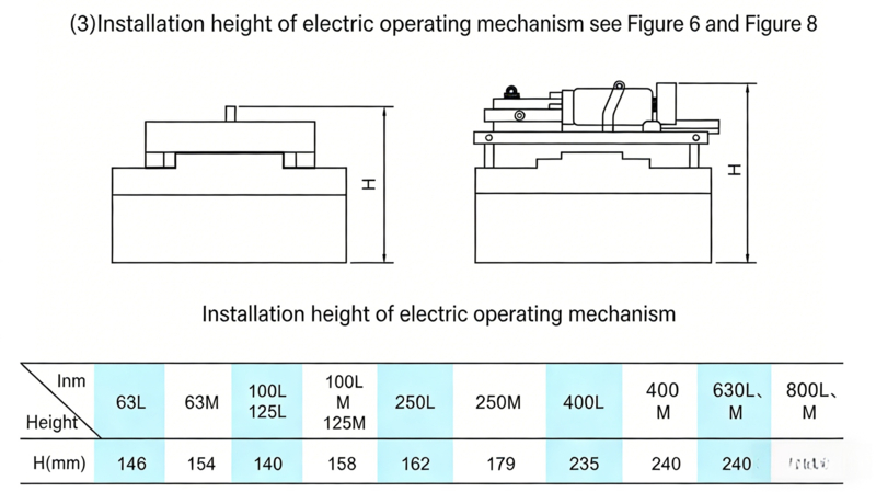
(1) The rated operating voltage of the electric operating mechanism includes: AC50Hz 110V, 230V; DC110V, 220V and other types.
(2) The power consumption of the motor of the electric operating mechanism is shown in Table 7.
| Circuit Breaker for Matching | Starting Current (A) | Power Consumption (W) | Circuit Breaker for Matching | Starting Current (A) | Power Consumption (W) |
|---|---|---|---|---|---|
| XYCM1-63 | ≤5 | 1100 | XYCM1-400 | ≤5.7 | 1200 |
| XYCM1-100(125) | ≤7 | 1540 | XYCM1-630 | ≤5.7 | 1200 |
| XYCM1-125 | ≤8.5 | 1870 | – | – | – |
1. Close and open the circuit breaker several times to check whether the operating mechanism of the circuit breaker is stuck and whether the mechanism action is reliable.
2. The “N”, “1”, “3”, “5” of the breaker are incoming terminals, and “N”, “2”, “4”, “6” are outgoing terminals, which are not allowed to be installed reversely.
3. The cross-sectional area of the connecting wire selected for the circuit breaker wiring must be adapted to the rated current. For the cross-sectional area of the main circuit wire when using copper wire or copper bar, refer to Table
| Rated Current (A) | 10 | 16 20 |
25 | 32 | 40 50 |
63 | 80 | 100 | 125 140 |
160 | 180 200 225 |
250 | 315 350 |
400 |
|---|---|---|---|---|---|---|---|---|---|---|---|---|---|---|
| Wire Cross-Sectional Area (mm²) | 1.5 | 2.5 | 4 | 6 | 10 | 16 | 25 | 35 | 50 | 70 | 95 | 120 | 185 | 240 |
| Rated Current (A) | Cable | Copper Bar | |||
|---|---|---|---|---|---|
| – | Cross-Sectional Area (mm²) | Quantity | Size (mm×mm) | Size (mm×mm) | Quantity |
| 500 | 150 | 2 | 30×5 | – | 2 |
| 630 | 185 | 2 | 40×5 | – | 2 |
| 800 | 240 | 3 | 50×5 | – | 2 |
Confirm that the terminal connections and fixing screws are tight and free of looseness before use.
The single-mounted circuit breaker shall be vertically fixed in a dry and ventilated place. It shall be easy to maintain and operate, with a distance of ≥1.5 meters from the ground.
6. Confirm that there is no short circuit or ground fault between the terminals or exposed live parts.
7. After the circuit breaker trips due to overload, check the cause to eliminate the fault, and reset the bimetallic sheet inside the circuit breaker before closing and energizing.
| Type | Item | XYCM1-63 | XYCM1-100, 125 | XYCM1-250 | XYCM1-400 | XYCM1-630 | XYCM1-800 | ||||||
|---|---|---|---|---|---|---|---|---|---|---|---|---|---|
| L | M | L | M | L | M | L | M | L | M | L | M | ||
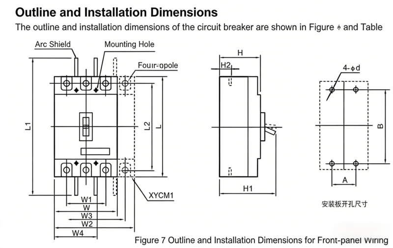
| Front Wiring | W | 78 | 92 | 107 | 150 | 182 | 210 | ||||||
| W1 | 50 | 60 | 70 | 96 | 118 | 140 | |||||||
| W2 | 103 | 122 | 142 | 198 | 240 | 280 | |||||||
| W3 | 75 | 90 | 105 | 144 | 174 | 211 | |||||||
| L | 135 | 150 | 165 | 257 | 270 | 280 | |||||||
| L1 | 169 | 185 | 295 | 456 | 476 | 490 | |||||||
| L2 | 117 | 132 | 144 | 224 | 234 | 243 | |||||||
| H | 74 | 82 | 68 | 86 | 86 | 103 | 107 | 107 | 112 | 116 | 116 | 116 | |
| H1 | 90.5 | 98.5 | 86 | 104 | 110 | 127 | 155 | 155 | 160 | 168 | 168 | 168 | |
| H2 | 20.5 | 24 | 24 | 38 | 42 | 41.5 | |||||||
| H3 | 52 | 63 | 52 | 60.5 | 61 | 74 | |||||||
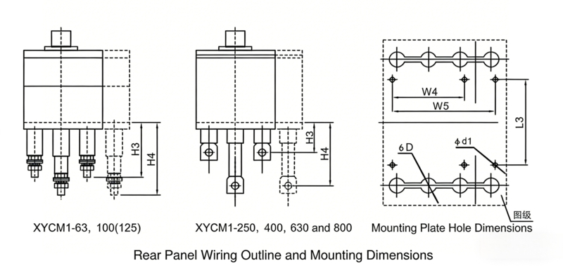
| Rear Wiring | H4 | 75 | 103 | 97 | 120.5 | 121 | 74 | ||||||
| W4 | 60 | 72 | 87 | 124 | 156 | 178 | |||||||
| W5 | 85 | 102 | 122 | 172 | 214 | – | |||||||
| φd1 | 5.5 | 5.5 | 5.5 | 6.5 | 7 | 7 | |||||||
| φD | 18 | 22 | 24 | 32 | 40 | 48 | |||||||
| L3 | 87 | 90 | 93 | 164 | 164 | 158 | |||||||
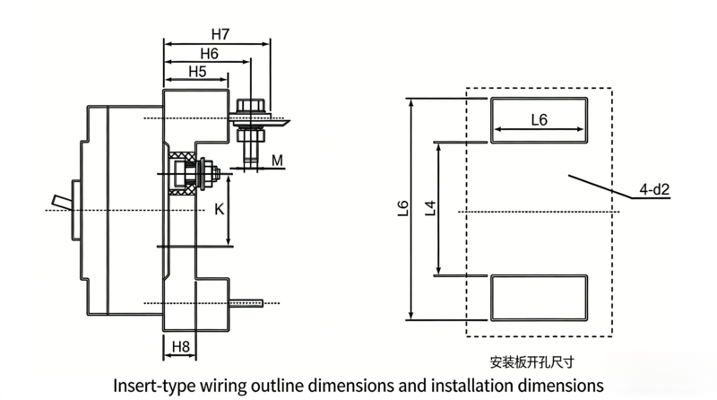
| Plug-in | L4 | 90 | 87 | 83 | 160 | 177 | 177 | ||||||
| L5 | 146 | 172 | 190 | 282 | 302 | – | |||||||
| L6 | 85 | 101.5 | 117 | 151 | 226 | 226 | |||||||
| H5 | 28 | 50 | 50.5 | 60.5 | 91 | 91 | |||||||
| H6 | 36 | 64 | 71.5 | 83.5 | 92 | – | |||||||
| H7 | – | 76 | 86.5 | 106.5 | 110 | – | |||||||
| H8 | – | 17.5 | 17.5 | 21 | 21 | – | |||||||
| K | 60 | 62 | 54 | 128 | 142 | 142 | |||||||
| C | 50 | 60 | 70 | 60 | 105 | 105 | |||||||
| φd2 | 5.5 | 6.5 | 6.5 | 8.5 | 12 | 12 | |||||||
| M | 5 | 8 | 8 | 12 | 14 | 14 | |||||||
| A | 25 | 30 | 35 | 44 | 58 | 70 | |||||||
| B | 117 | 129 | 126 | 194 | 200 | 243 | |||||||
| Installation Dimensions | φd | 3.5 | 4.5 | 4.5 | 7 | 7 | 7 | ||||||