Address
304 North Cardinal St.
Dorchester Center, MA 02124
Work Hours
Monday to Friday: 7AM - 7PM
Weekend: 10AM - 5PM
| Model | Frame Grade Rated Current Inm(A) | Pole Number | Rated Insulation Voltage Ui(V) | Rated Working Voltage Ue(V) | Rated Current In(A) | Rated Short-circuit Breaking Capacity Icu=Isc (kA) | cosφ | Arc Distance (mm) |
|---|---|---|---|---|---|---|---|---|
| DZ15-40 | 40 | 2 | 380 | 220/380 | 6, 10, 16, 20, 25, 32, 40 | 3 | 0.9 | ≤50 |
| DZ15-40 | 40 | 3 | 380 | 380 | 6, 10, 16, 20, 25, 32, 40 | 3 | 0.9 | ≤50 |
| DZ15-100 | 100 | 3 | 380 | 380 | 10, 20, 25, 32, 63, 80, 100 | 5 | 0.7 | ≤70 |
2. The protection characteristics of the overcurrent release are shown in Table 2 and Table 3, and the setting accuracy of its short-circuit instantaneous protection characteristics is ±20%.
| Rated Current (A) | 6, 10 | 16, 20 | 25 | 32 | 40, 50 | 63 | 80 | 100 |
|---|---|---|---|---|---|---|---|---|
| Wire Cross-sectional Area (mm²) | 1.5 | 2.5 | 4 | 6 | 10 | 16 | 25 | 35 |
4. After the circuit breaker is installed, it shall be inspected in accordance with the installation requirements to ensure that its fixed connection parts are firm and reliable. Operate the circuit breaker repeatedly for several times to confirm that the operating mechanism is flexible and reliable before putting it into use.
5. The protection characteristics of the circuit breaker have been adjusted by the manufacturer at the factory. Users shall not adjust them arbitrarily during use to avoid affecting the protection performance.
6. If the circuit breaker trips due to faults (overload or short-circuit) in the control circuit, the operating handle will be in the tripped position. After identifying the cause and eliminating the fault, the circuit breaker can be reset and put into operation again.
7. After the circuit breaker interrupts a short-circuit, the cover must be opened to inspect the contacts. If the contacts are severely burnt or pitted, maintenance or replacement shall be carried out.
8. During use, storage or transportation, the circuit breaker shall not be exposed to rain, snow, or subjected to dropping impacts.
1. Ambient air temperature:
a. The upper limit of ambient air temperature is +40℃;
b. The 24-hour average ambient air temperature shall not exceed +35℃;
c. The lower limit of ambient air temperature is -5℃.
Note: For operating conditions where the upper limit of ambient air temperature exceeds +40℃ or the lower limit is lower than -5℃, the user must consult with our factory when placing an order.
2. Altitude: The altitude of the installation site shall not exceed 2000m.
3. Atmospheric conditions: At the maximum temperature of +40℃, the relative humidity of the atmosphere shall not exceed 50%. Higher relative humidity is allowed at lower temperatures, e.g., 90% at 20℃. Special measures shall be taken for condensation occasionally formed on the product due to temperature changes.
4. Pollution degree: The pollution degree of the installation site is class 3.
5. Installation category: The installation category of the circuit breaker is class II.
6. Installation conditions: The circuit breaker shall be installed individually or in a power distribution cabinet in accordance with the instruction manual provided by our factory. The installation position shall be vertical, and the inclination angle with the vertical plane shall not exceed 5°.
7. Installation environment conditions:
a. Install in a place free from significant shaking, impact and vibration;
b. Install in a place free from rain and snow;
c. The installation site shall be free from explosive hazardous media, and there shall be no gases and dust in the medium that are sufficient to corrode metals and damage insulation.
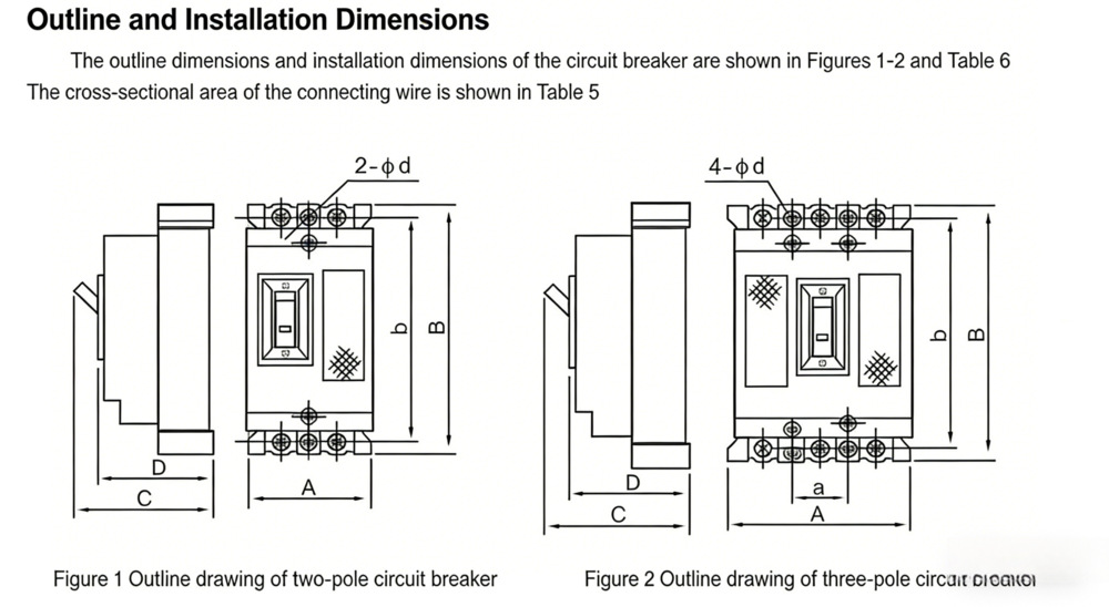
| Model | Pole Number | Outline Dimensions | Installation Dimensions | |||||
|---|---|---|---|---|---|---|---|---|
| A | B | C | D | a | b | Φd | ||
| DZ15-40 | 2 | 53 | 134 | 88 | 73.5 | / | 120 | 2-Φ5 |
| 3 | 78 | 134 | 88 | 73.5 | 25 | 120 | 4-Φ5 | |
| DZ15-100 | 3 | 96 | 147 | 96 | 80 | 30 | 130 | 4-Φ7 |
Users shall specify the following contents when placing an order:
1. Name and model of the circuit breaker;
2. Rated current of the release;
3. Number of poles;
4. Application purpose;
5. Order quantity.
Example: Order 100 pieces of DZ15-40/3901 molded case circuit breakers, with 32A rated release current, 3 poles, for power distribution use.
| Ambient Air Temperature | Test Current | Test Time | Expected Result | Initial State |
|---|---|---|---|---|
| +30±2℃ | 1.05In | ≥1h | No Tripping | Cold State |
| 1.3In | <1h | Tripping | Hot State | |
| At Any Suitable Temperature | 3.0In | ≥2s | Recoverable | Cold State |
| 10.0In | <0.2s | Tripping | Cold State | |
| +20±2℃ | 1.05In | ≥1h | No Tripping | Cold State |
| 1.3In | <1h | Tripping | Hot State |
Note: The circuit breaker shall be recoverable when energized with 3In current for the specified time, then the test current is reduced to 90% of the rated current, and the circuit breaker shall not trip.
| Ambient Air Temperature | Test Current | Test Time | Expected Result | Initial State |
|---|---|---|---|---|
| +30±2℃ | 1.05In | ≥2h | No Tripping | Cold State |
| 1.2In | <2h | Tripping | Hot State | |
| 1.5In | <2min | Tripping | Hot State | |
| 7.2In | 2s<t≤10s | Recoverable | Cold State | |
| At Any Suitable Temperature | 12.0In | <0.2s | Tripping | Cold State |
| -5±2℃ | 1.05In | ≥2h | No Tripping | Cold State |
| 1.3In | <2h | Tripping | Hot State | |
| +40±2℃ | 1.0In | ≥2h | No Tripping | Cold State |
| 1.2In | <2h | Tripping | Hot State |
Under specified conditions, the mechanical and electrical life of the circuit breaker is expressed by the number of operating cycles (see Table 4).
| Type of Residual Current Circuit Breaker | Rated Operating Conditions | Operating Cycles per Hour | Number of Operating Cycles | ||||
|---|---|---|---|---|---|---|---|
| Closing | Breaking | cosφ | With Load | Without Load | Total | ||
| For Distribution Protection | Un In | Un In | 0.8 | 120 | 1500 | 8500 | 10000 |
| For Motor Protection | Un 6In | 0.17Un In | 0.35 | 120 | 1500 | 8500 | 10000 |
Note: During each operating cycle, the maximum closing time of the circuit breaker shall be 2s. When the circuit breaker for motor protection is closed with 6In current, the minimum closing time shall be 0.1s.
4. Power Frequency Withstand Voltage
The circuit breaker can withstand the power frequency withstand voltage test of AC 50Hz, 1890V for 5s without flashover and breakdown.
5. Impulse Withstand Voltage: 6kV
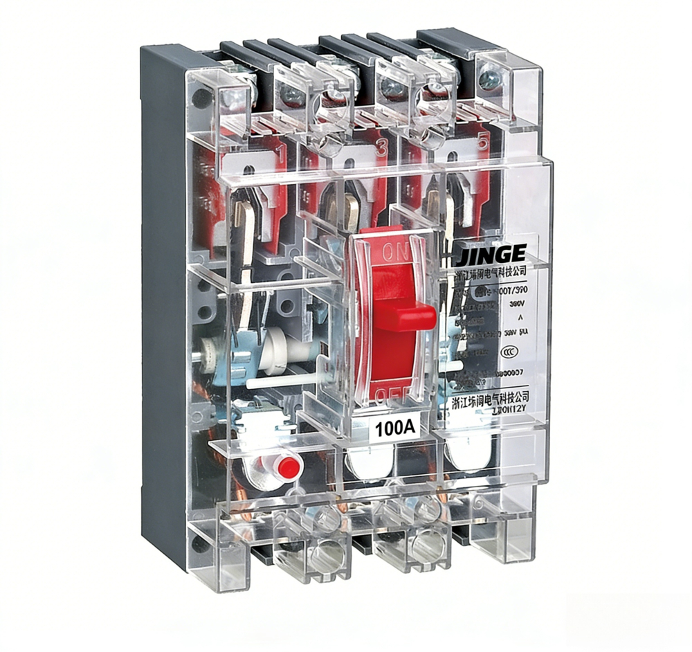
1. The circuit breaker is mainly composed of an operating mechanism, overcurrent release, contact series, arc extinguishing cover, base and cover, and all components are assembled in a plastic shell.
2. The base and cover of the circuit breaker are pressed with thermosetting insulating plastic, which has good insulation performance. The operating mechanism has the functions of quick closing and quick opening of contacts. Its “close”, “open”, “re-engage” and free tripping positions are distinguished by the handle position, and the circuit breaker is marked with “close” and “open” indicators.
3. The circuit breaker has overload and short-circuit protection functions. Its overcurrent release adopts a silicon oil resistance hydraulic release, which can provide an ideal inverse time-delay overcurrent protection characteristic.
4. The circuit breaker is available in single-pole, two-pole, three-pole and four-pole forms to meet the requirements of users for selecting different phase lines. The full series of circuit breakers are installed with screws, which is firm and reliable.
1. Before installation, check whether the technical parameters on the nameplate are consistent with the actual requirements.
2. The circuit breaker shall be installed in accordance with specified requirements: the incoming terminal at the upper part of the circuit breaker is the power side, the outgoing terminal at the lower part is the load side, and the upward position of the handle is the contact closing position.
3. When wiring the circuit breaker, the cross-sectional area of the selected connecting wire must be suitable for the rated current. For PVC insulated copper wires, refer to Table 5 for the cross-sectional area.